The
model has this vent is in the wrong location and orientation.
Do NOT use the marked area on the port side Deckhouse
roof suggested by the manufacturer.
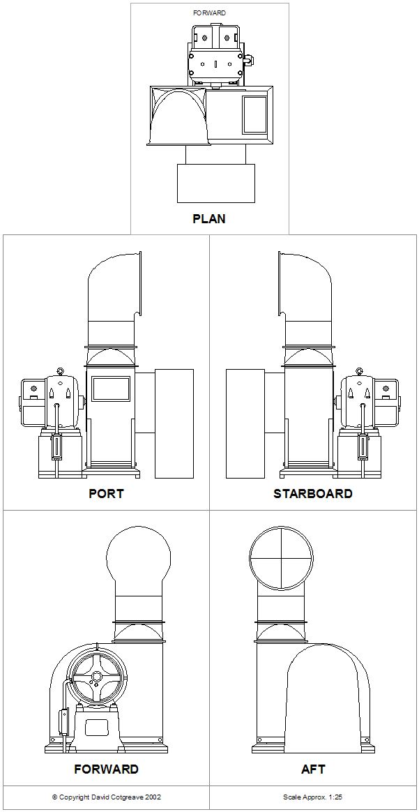
Rotate
the existing part so that the motor faces you. (The motor
is the protruding `knob' with the small cross shape on
the end of it opposite the curved downward duct). This
is the correct orientation for the part. Now cut off the
curved duct opposite the motor and file flat.
As
you will be turning the vent in a different direction
to the one the model builders had intended you may want
to prep the motor unit as described in the Cowl
Vents Attached to Motor Units section of the Vent
Overview
 To
create the new duct cut a rectangle of 2mm thick sheet
styrene or one of the parts tabs from the sprue tree to
approx. 7.5mm to 4mm and round the top corners with a
file To
create the new duct cut a rectangle of 2mm thick sheet
styrene or one of the parts tabs from the sprue tree to
approx. 7.5mm to 4mm and round the top corners with a
file
 Cut
out a rectangle as shown opposite. Cut
out a rectangle as shown opposite.
There was a
small circular duct that joined to the two parts together
(see top diagram). To create this place the two parts
together allowing the motor unit to sit 1mm over the inboard
edge of the duct and put a mark on the back of the duct
directly opposite the motor unit. Put the motor unit aside
for one moment and using a 1.5mm bit drill a hole through
where you put the mark.
Line the two
parts up again and continue drilling into the back of
the motor unit. Be careful not to drill too much or you
will come out of the other side and wreck the vent.
 Before
gluing the parts together you have to reduce the height
of the widest section of the duct by 1mm to allow for
the raised platform that funnel no 1 sits on. Before
gluing the parts together you have to reduce the height
of the widest section of the duct by 1mm to allow for
the raised platform that funnel no 1 sits on.
 Dab
a small drop of glue in the hole in the back of the motor
unit and insert a short length of 1.5mm styrene rod. Allow
to dry. Dab
a small drop of glue in the hole in the back of the motor
unit and insert a short length of 1.5mm styrene rod. Allow
to dry.
When dry put
a drop glue into the hole in the duct and push the rod
through the hole.
When dry trim
the excess rod from the back of the duct and sand smooth.
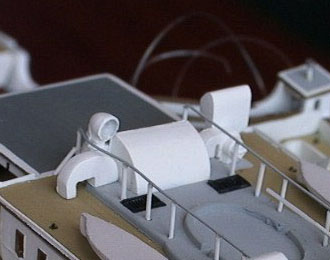
After making
the few modifications suggested in the Cowls
section of the Vents Overview glue the cowl vent on the
port side of the motor unit facing the stern.
When placed
correctly the vent's base should be slightly overlapping
the port side face- of the large rectangular centre vent
(H23B) in front of No. 1 funnel and the duct should cover
the old Deck marking for the vent.
Note:
If you are going to add the 7 poles and safety lines
down each side of No. 1 funnel (See
MISC section) the safety line will pass along the
inside edge of the cowl over top of the motor housing.
|